SolidWorks Primitives: Which Base Shape to Start With
SolidWorks Primitives: Which Base Shape to Start With Pick the wrong starting shape in SolidWorks and you won't find out until three feature edits later, when the whole tree falls apart and you're…
2026-08-14
SolidWorks Primitives: Which Base Shape to Start With
Pick the wrong starting shape in SolidWorks and you won't find out until three feature edits later, when the whole tree falls apart and you're rebuilding from scratch. SolidWorks is a parametric CAD system, which means every part you build starts as a sketch and turns into 3D geometry through features like extrude, cut, mirror, and pattern [1][2][3]. Before any of that happens, though, you make one decision that shapes everything downstream: which primitive to start with.
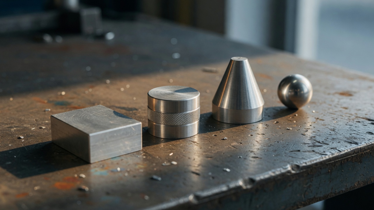
Block, cylinder, cone, and sphere are the most common starting shapes, with wedge, torus, and pyramid showing up in broader solid-modeling work [1][4][2][5]. That first choice sounds small. It isn't.
Why the Primitive Choice Isn't Just a Formality
Most tutorials treat primitive selection as a throwaway step, something you click past on the way to the "real" modeling work. That's backwards. The primitive you start with sets the geometric logic for everything that follows, and SolidWorks behaves less like a drawing tool and more like a program you're writing one feature at a time [6][2]. Every extrude, cut, and pattern you add later references what came before it. Start with a shape that doesn't match your part's underlying geometry, and you're not saving time. You're setting up a rebuild.
Here's the obvious approach everyone defaults to: open SolidWorks, start sketching, and figure out the shape as you go. It feels fast. It isn't. Sketching without a clear primitive in mind is how you end up with an unconstrained sketch that looks fine until you try to edit it, at which point the geometry shifts in ways you didn't ask for [6][2][3]. The fix isn't more caution. It's picking the right base shape before you draw your first line.
The Decision Rule: Matching Shape to Part
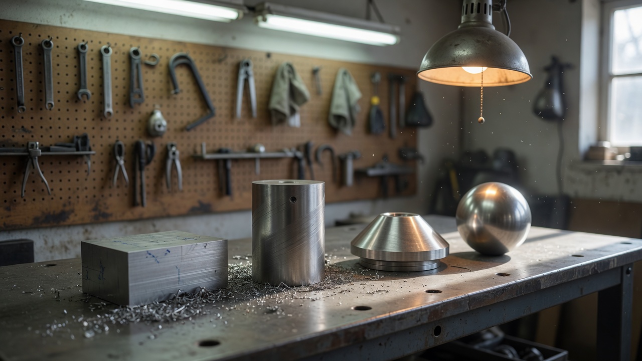
The rule is simpler than most training material makes it sound. If your part is roughly block-like, a bracket, housing, or mounting plate, start with a block primitive. If it's cylindrical, a shaft, bushing, or standoff, start with a cylinder. Conical geometry, like a nozzle or a tapered fitting, starts as a cone. Spherical parts, ball joints, knobs, certain fittings, start as a sphere.
This isn't a hard boundary. It's a starting point that saves you feature-tree cleanup later.
Why does this matter so much? Because SolidWorks builds every downstream feature relative to the primitive's geometry. A cylinder gives you a clean axis to pattern around. A block gives you flat faces to reference for cuts and fillets. Start with the wrong shape and force the geometry to comply through extra cuts and workarounds, and you've built a part that's fragile the moment someone, including future you, tries to change a dimension.
- Block-like parts: brackets, enclosures, mounting plates, most sheet-metal-adjacent geometry
- Cylindrical parts: shafts, bushings, standoffs, pins, rollers
- Conical parts: nozzles, tapered fittings, funnels
- Spherical parts: ball joints, knobs, spherical bearings
None of these are universal laws. A part that's mostly cylindrical but has a rectangular mounting flange might still start as a cylinder, with the flange added as a secondary feature. The scope of this rule depends on your part's dominant geometry, not a rigid category system. If you're a one-person shop turning around five parts a week, this rule saves you real time. If you're managing a library of a few hundred parts across a design team, the rule still holds, but you'll want it documented as a team standard so everyone starts from the same logic.
Sketch Primitives vs. Solid Primitives: A Real Source of Confusion
Here's something that trips up a lot of people learning SolidWorks, and even some who've used it for years. The word "primitive" gets used two different ways. Informally, practitioners use it to describe basic 2D sketch geometry, lines, circles, arcs, rectangles, the entities you draw before extruding anything [2]. Formally, in broader solid-modeling instruction, "primitive" refers to the 3D building blocks themselves: block, sphere, cylinder, cone, wedge, torus, pyramid [1][4][7][5][8].
These aren't competing definitions. They describe two stages of the same build path: sketch primitives become solid primitives through a feature operation, most commonly extrude [2][9][3]. But if you're reading a tutorial or talking to a colleague and you don't know which meaning is in play, you'll misapply the advice. A tip about "primitive selection" for sketch geometry doesn't translate directly to a tip about primitive selection for solid modeling, even though the word is identical.
Knowing which one someone means changes what you should actually do next. If a training resource is talking about sketch primitives, the takeaway is about constraint discipline and entity selection. If it's talking about solid primitives, the takeaway is about which base shape to extrude from. Conflate the two and you'll apply the wrong lesson to the wrong stage of your build.
The Workflow That Keeps a Model Editable
Picking the right primitive is step one. Step two is sequencing your features so the model stays editable months later, when a client changes a spec or a part needs a revision. SolidWorks is parametric and feature-driven, which the research describes as closer to visual programming than freehand drawing [6][1][2][3]. Every feature you add depends on the ones before it, the same way a line of code depends on variables declared earlier.
The sequence that holds up under real-world editing looks like this: start with your primitive, build a constrained sketch on the appropriate plane, extrude or cut to establish the core geometry, then use mirror and pattern for any repeated or symmetric features. Skip a step, or build features in a disorganized order, and you get a model that works today and breaks the next time someone opens it.
A posting schedule without a locked voice builds volume, not a brand. The same logic applies here: a feature tree without a locked sequence builds a part, not a model you can actually maintain. Unconstrained sketches and features added in a rush, out of logical order, are the two most common reasons a SolidWorks model becomes hard to edit [6][2][3]. Neither failure shows up immediately. Both show up the first time someone tries to change a dimension, and that's exactly when you don't have time to rebuild from scratch.
Mirror and Pattern: Speed That Depends on Discipline
Mirror and pattern get cited constantly as SolidWorks' fastest tools for repeated or symmetric geometry [6][1][2][9][3]. That's true, but it's also where a lot of models quietly break. Mirror and pattern don't save time on their own. They save time when the base primitive and its constraints were set up correctly first.
Think about it this way: if you pattern a feature off a sketch that isn't fully constrained, you're not multiplying good geometry, you're multiplying a problem. Every copy inherits whatever ambiguity existed in the original. Fixing that after the fact means undoing the pattern, fixing the base feature, and reapplying the pattern, which costs more time than if you'd constrained the sketch properly the first time.
So treat mirror and pattern as a reward for good setup, not a shortcut around it. If your base primitive is solid and your sketch is fully constrained, patterning is genuinely fast. If it isn't, patterning just makes the fix bigger later.
When a Primitive Isn't the Right Call
Not every part should start as a clean primitive, and pretending otherwise oversells the rule. If your geometry is genuinely irregular, an organic shape, a complex surface, a part reverse-engineered from a scan, forcing it into a block-cylinder-cone-sphere framework wastes more time than it saves. In those cases, sketching from scratch or working from a surface model makes more sense.
The real decision depends on three things: how close your part's geometry is to a standard primitive, how complex the finished part needs to be, and what your shop or team is actually equipped to build and revise. A small shop with one or two designers benefits enormously from defaulting to primitives, because it standardizes the workflow across every job. A team building highly custom, one-off geometry every time may find the primitive framework less useful and should lean on surface modeling and freeform sketching instead.
Frequently Asked Questions
What are primitives in SolidWorks?
Primitives are the basic starting shapes for solid models, most commonly block, cylinder, cone, and sphere, with wedge, torus, and pyramid used less often [1][4][2][7][5][3]. You build on top of these shapes using features like extrude, cut, mirror, and pattern.
Should I always start with a primitive instead of sketching freehand?
Not always. Primitives work best when your part's geometry is reasonably close to a standard shape. Highly organic or reverse-engineered geometry often needs surface modeling or freehand sketching instead. The right call depends on part complexity, your shop's capability, and how much setup time a primitive would actually save.
Why does my SolidWorks model break every time I try to edit it?
The two most common causes are unconstrained sketches and a disorganized feature tree [6][2][3]. If your original sketch isn't fully constrained, or your features were added out of logical order, small edits can cause geometry to shift unpredictably. Fixing the sketch constraints and cleaning up feature order usually solves it.
What's the difference between sketch primitives and solid primitives?
Sketch primitives are basic 2D entities, lines, circles, arcs, rectangles, that you draw before extruding anything [2]. Solid primitives are the 3D building blocks, block, cylinder, cone, sphere, and similar shapes [1][4][7][5]. Sketch primitives become solid primitives through a feature operation like extrude [2][9][3].
Where This Goes Next
None of this replaces the judgment you've built modeling real parts for real jobs. That judgment, which primitive fits which geometry, when to break the rule, how your shop actually handles handoff, is exactly the kind of expertise that's hard to find in generic tutorials and easy to lose track of when you're too busy building parts to write about how you build them. If your team has that expertise and no time to turn it into consistent content, that's a gap worth closing before a competitor closes it first.
Sources
- SolidWorks - Lessons | PDF | Extrusion | Geometry - Scribd (scribd.com)
- Solidworks Tutorial | PDF | Curve | Plane (Geometry) (fr.scribd.com)
- TP1 Solidworks | PDF | Logiciel - Scribd (scribd.com)
- SolidWorks Modeling Guide | PDF | Circle | Triangle (fr.scribd.com)
- solid modeling | PDF (scribd.com)
- Schwarz P (Primitive) TPMS Modeling in SolidWorks (grabcad.com)
- BOX Sphere Cylinder Cone Wedge Torus Pyramid / PYR Psolid (id.scribd.com)
- 4.16 Solid Primitives | Geometry for Modeling and Design | Peachpit (peachpit.com)
- Solidworks Student... (courses.ideate.cmu.edu)
Researched from 21 vetted sources · average source authority DR 87